Electronics
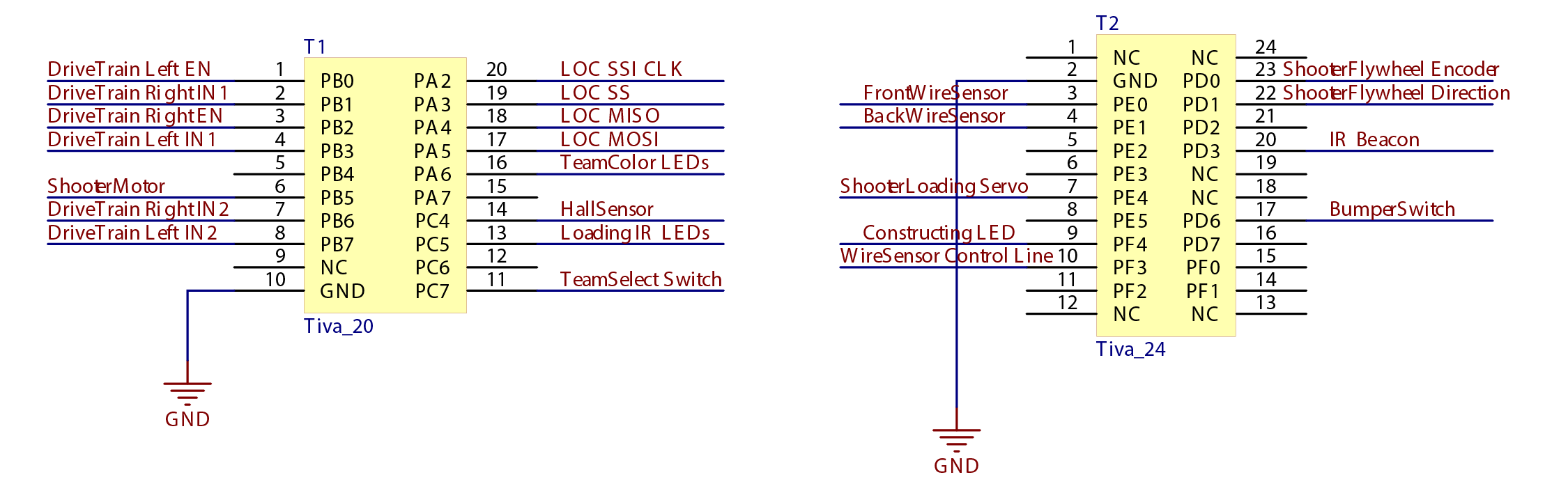
TIVA Pinout
Power Distribution
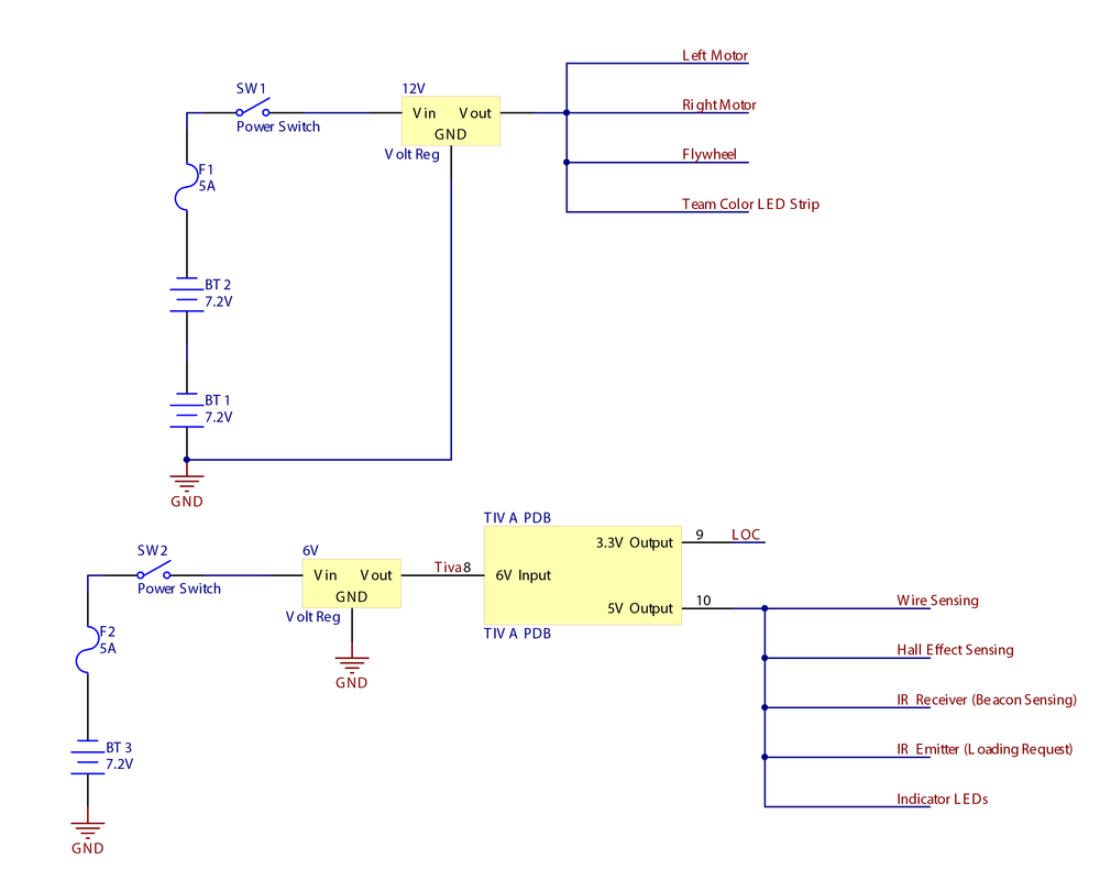
Two 7.2 V batteries were used to supply power to the drive train motors and flywheel motor. A fuse was added in series for safety. A voltage regulator was used to maintain a constant voltage regardless of battery consumption. Last, a switch was used to toggle the power on/off.
The TIVA was powered by a similar circuit with the only difference being that only one 7V batter was used. The voltage regulator regulated the voltage to 6V, which is the appropriate voltage for the TIVA. All ICs were then powered using the TIVA's 3.3V or 5V outputs.
The TIVA was powered by a similar circuit with the only difference being that only one 7V batter was used. The voltage regulator regulated the voltage to 6V, which is the appropriate voltage for the TIVA. All ICs were then powered using the TIVA's 3.3V or 5V outputs.
Wire Following
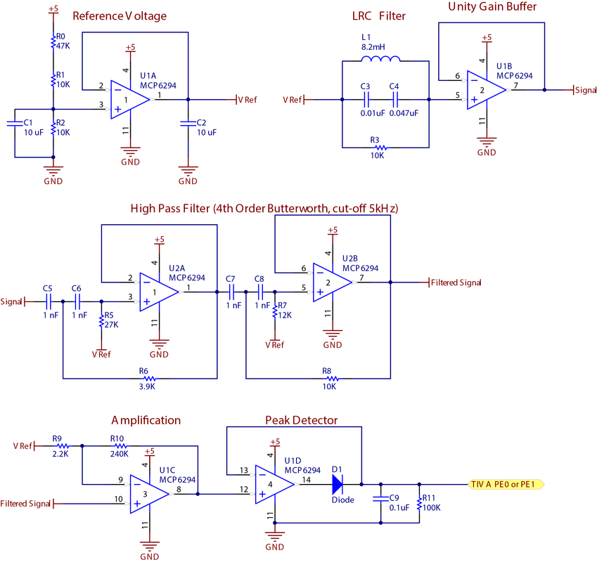
To effectively follow the line on the board game, SushiBot had two pairs of inductors for detecting the wire frequency; one pair in the front and one in the back. The inductors' signal was filtered with a 4th order Butterworth filter, amplified, and passed through a peak detector circuit. When the bot was moving forward, the front sensors were selected using a 74HC066 analog switch. When the bot was moving in reverse, the back sensors were selected.
Checking-in (Hall Sensors)
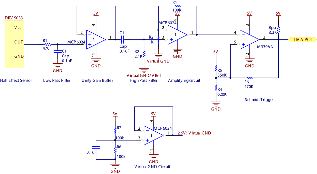
To check-in, SushiBot use a hall sensor to detect the staging areas' frequency. The circuit consists of an AC coupling, unity gain buffer, 2nd order low pass and high pass filters, amplification and comparator.
IR Beacon Detector
Shooting to the correct bucket required aligning first. To accomplish this task, SushiBot had a phototransistor that picked up the IR light emitted by each of the buckets' beacons. The phototransistor was used in a trans-resistive circuit, passed through a high-pass filter, amplifier, and comparator to produce a clean square wave signal input to the Tiva.
Loading (IR emitters)
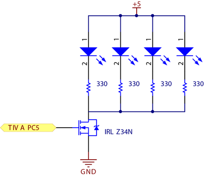
To load COWs, SushiBot had to pulse an IR signal to the IR receiver at the loading stage. The accomplish this, SushiBot used a fan of four IR emitters controlled a MOSFET.
Shooter
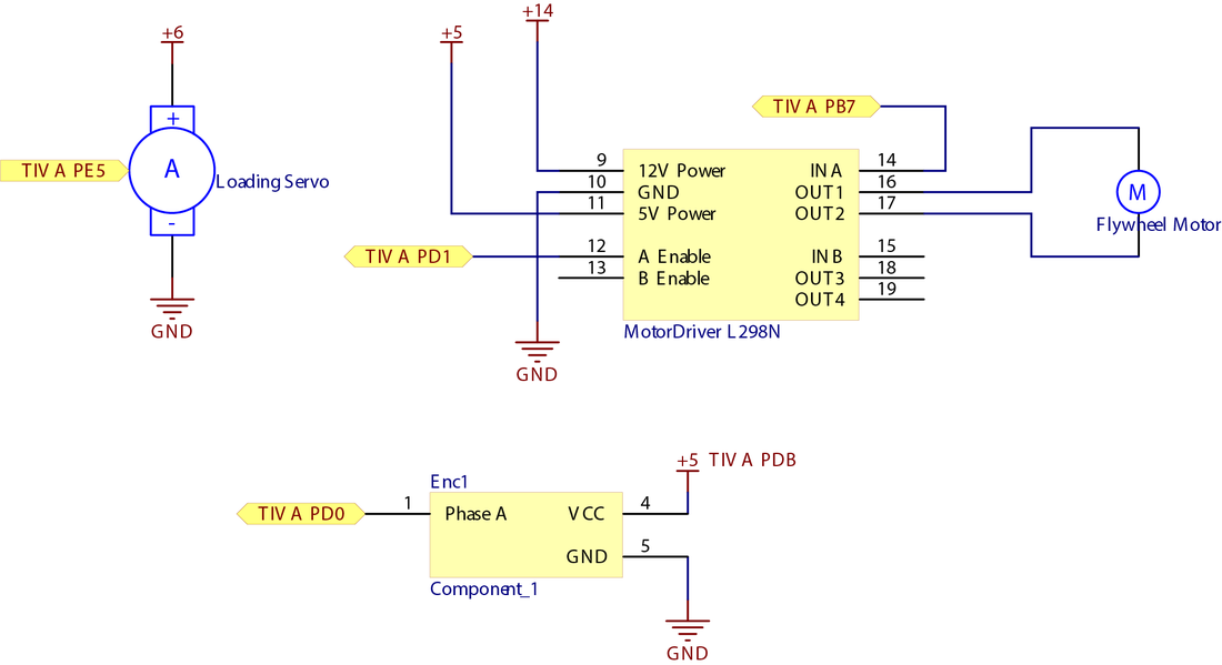
The shooting mechanism had a DC motor with a mounted optical encoder to control the flywheel speed, and a gating servo for loading and releasing COWs in the flywheel chamber. The DC motor was controlled using a L298N motor driver module.
Drive Train
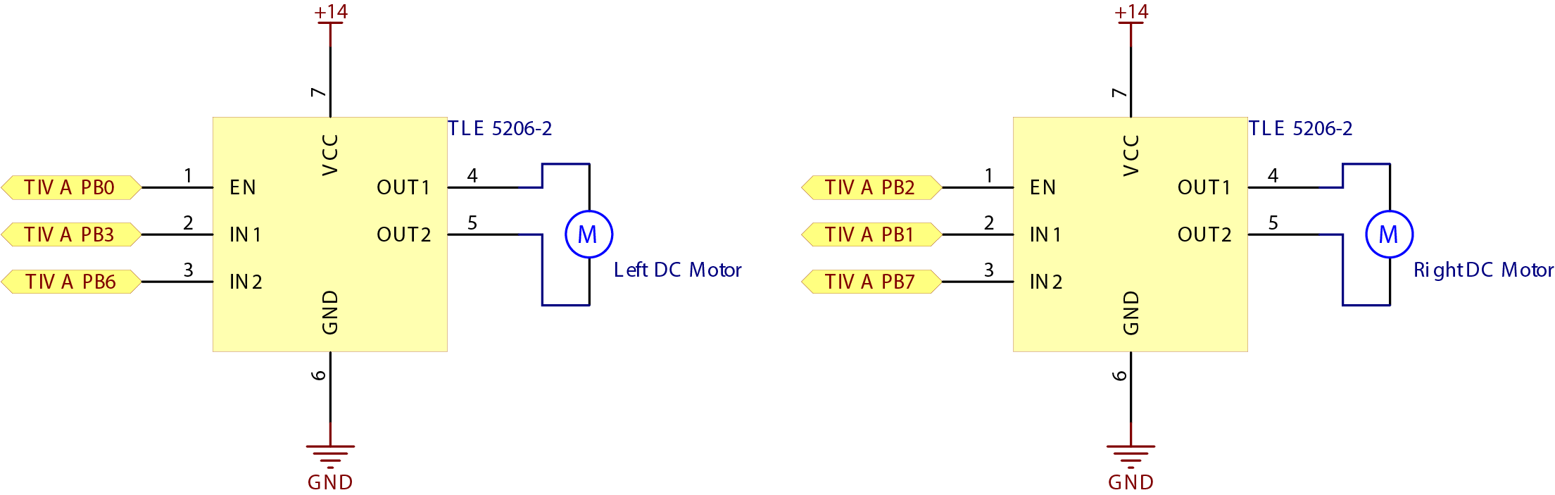
SushiBot had two motors for the drive train. Each was controlled using a TLE 5206-2 motor driver.
Team Color Selection
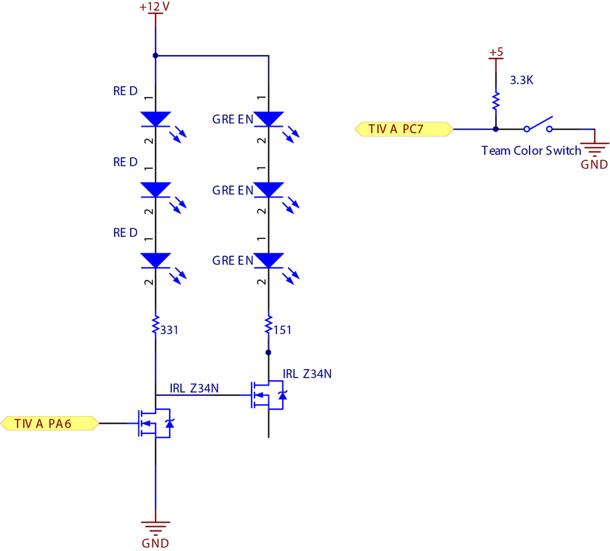
An RGB LED strip was used to visually show which team color SushiBot was playing. A MOSFET was used to control switching between green team and red team.
A switch was used to manually select which team color SushiBot would be.
A switch was used to manually select which team color SushiBot would be.
