Mechanical Design
|
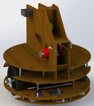
Development MethodologyDue to the time constraints and design requirements of the project an agile development approach was utilized to ensure multiple design iterations could be fabricated and tested. Ultimately, we decided on a multi-tiered design with a custom flywheel shooter. A lower platform was placed below the drivetrain of the bot to house all electromagnetic sensing circuitry.
|
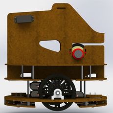
Right Side
|
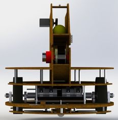
Front
|
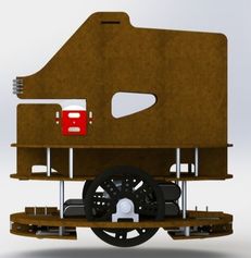
Left Side
|
CHassis
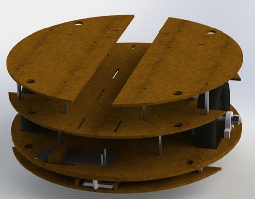
The main design goal of the chassis was to provide a rigid foundation that provided ample mounting space for the various subsystems. The chassis was created out of laser-cut duron due to the ease of fabrication. Standoffs were used to create a multi-level chassis, allowing for the mounting of the drive-train, electronics, and the shooter. All required subsystems were packaged and arranged to keep the center of mass over the wheels and as low as possible. Two drive wheels were mounted centered on the robot to minimize the difference between driving forward and reverse. Cantilevered spring steel was used as suspension for two caster wheels mounted at the front and rear. This ensured the robot was fully supported at all times, allowing for smoother driving.
PowerTrain
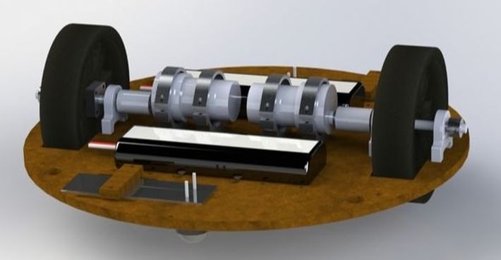
The power train consisted of two DC motors powered by two NiMH rechargable batteries. The DC motors were connected with flexible couplers to ¼ inch shafts which were mounted on the 4 inch wheels. The ¼ inch shaft was supported by pillow bearings at each end to take the load off of the motor shaft. The motors were mounted with off-the-shelf mounts and custom duron shims to ensure proper fit and shaft alignment.
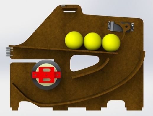
SHOOTER
|
The goal of the shooter was to be robust and consistent at various shooting distances. To achieve the design goals while maintaining simplicity, a flywheel-style shooter was chosen. The design consisted of a flywheel driven by a DC motor mounted to a fully enclosed ramp. The shooter was fabricated out of duron utilizing a kerf cut on the ramp to ensure the desired launch angle was achieved. The motor was mounted to the shooter side walls with custom 3D printed parts to ensure the desired flywheel position was achieved. An optical encoder was mounted to the shaft of the motor to implement PD speed control to ensure consistent shooting at various distances.
|
|
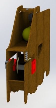
Loading Mechanism
The design goal of the loading mechanism was to accurately dispense one ball at a time while adding as little energy to the ball's motion as little as possible. To achieve the design goals, a custom laser cut duron attachment was fit to a servo motor.
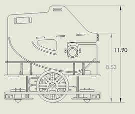
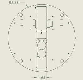
System Dimensions
|
|
Per the project requirements the entire robot robot can fit inside of a 12 inch cube.
